To Whom It May Concern:
Be it known that I, Daniel McFarland Cook, of Mansfield, in the county of Richland and State of Ohio, have invented an Electro-Magnetic Battery, of which the following is a specification:
My invention relates to the combination of two or more simple or compound helices and iron cores or magnets in such a manner as to produce a constant electric current without the aid of a galvanic battery.
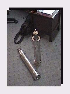
Figure 1 represents the different parts of a compound helix and iron core. Fig. 2 is a perspective view of my invention.
In carrying out my invention I do not confine myself to a particular mode of constructing a helix or helices, or to any particular size of wire, observing only that the quantity of wire in the several helices is sufficient to produce the results, using less or more wire in the helices to suit the purpose for which they are designed; also using such material for insulating the helices as will secure a proper action. I prefer, however, in common , to use the same size of wire in the construction of either simple or compound helices. In the use of the simple helices for convenience, and to favor the insulation in the resistance to obtain a sufficient tension and quantity of current for action, it is desirable to use a long iron core, A, Fig. 1, say two, three, or even six feet in length, and two, three, or more inches in diameter; also a large copper wire of good conductive quality, the wire being well insulated with silk, shellac, or paraffin only, the latter being objectionable as it is liable to be melted by the heating of the helix while in action. The iron core A may be a solid bar or a bundle of iron wire, the latter giving higher tension to the current with equal length and fineness of wire. In any event the wire may be fine or coarse; but I prefer to use No. 16, or even heavier wire, as the result is powerful in proportion to the size and length of the wire. In the use of the compound helices it is preferable, in some cases, to use a small wire, say No.30, or even less, for a primary helix, and No.16, or even larger, for a secondary helix. By this combination the initial secondary current of the primary helix being very small in quantity in comparison to the terminal secondary current of the secondary helix offers but little resistance to the terminal secondary, hence a quicker action is secured; or the primary helix may be made of un-insulated wire coiled into a solid helix, being insulated only between the coils, in which case there is but little or no opposing initial secondary current. Helices alone with large quantities of wire will produce similar results. A ribbon spiral may be substituted for the secondary helix, say of three, six, twelve, or twenty-four inches in width and of any convenient length, but always of sufficient length to raise the tension of the terminal current to a degree necessary to reproduce itself by its action on the primary helix. In the use of compound helices it is important that the secondary coil should be wound on in the same direction as the primary coil, and that the poles or wires should be connected to the opposite poles of the primary coil B. The action will then be as follows: The terminal secondary current of the secondary helix C will circulate through the opposite primary coil B, while at the same instant a terminal secondary current from the primary helix B will be developed and circulate through the opposite secondary helix C, both currents flowing in the same direction in the opposite helices B C, and produce a combined magnetic action upon the iron bar A in the center; the opposing initial secondary currents of the two helices B C being overpowered do not manifest themselves in the main circuit D of the battery, there being eight distinct currents developed in the action of one entire circuit of the two pairs of helices, two terminal and two initial secondary currents to each pair of helices, the four initial secondaries constantly opposing the circulation of the four terminal secondary currents; but the initial secondaries being of much lower tension and less in quantity than the terminal secondary are consumed or taken up by the terminal, leaving a sufficient surplus terminal to overcome the resistance of the primary wire and charge the bar A to a degree necessary to reproduce itself in an opposite secondary coil. By this means a constant current is kept up in the several helices. The coils may be composed of from five hundred to one thousand feet or more primary coil, and less or more secondary coil, in any event the more coil and the better the insulation the more powerful the result. In the use of simple helices, or two coils only, any size wire may be used, only so that the insulation is effectual and the quantity of wires is sufficient. The longer and the larger the wire or coil the more powerful the result, one thousand or more feet being preferable. The poles of the two helices being connected the action is the same as in the compound helices, there being but four currents developed, two initial and two terminal currents, the latter flowing constantly in the same direction – in effect there being but one current in the same direction.
The mode of producing or starting the action in the helices consists in the use of a steel or electromagnet, or a helix, around one of the helices, and causing a secondary current in the enclosed helix by means of a battery current in the outer one; the action then in either the simple or compound helices increases in quantity to the maximum capacity of the wires to conduct with the existing tension of the current. If, now, the circuit is broken the current instantly ceases, and can only be restored by the same means that it was first produced; hence to allow the use of the main circuit for common purposes I introduce a rheostat or resistance of any kind into the circuit, so that a small portion of the current only will flow along the resistance, by which means the action in the helices is feebly maintained when the main circuit is broken, and instantly restored when it is closed to its full force. By this means the action becomes in effect the same as the common battery currents, and may be used for similar purposes. For the purpose of preventing the heating of the helices caused by the intensity of the action, and to prevent circulation of the initial secondary currents in the main circuit, a rheostat of any convenient form may be made to constitute a part of the main circuit D. The alternate changes of the iron cores or magnets may be used for producing electro-magnetic motion, or motion to a wheel of any suitable device.
Having described my invention, what I claim as new, and desire to secure by Letters Patent, is –
The combination of two or more simple or compound helices, in the manner and for the purpose set forth.
Witness:
A. J. Mack
J. W. Jenner